Senographe DS Gantry Communication Failure & PL104 Board Repair
A mammography system could not initialize its gantry and reported multiple communication and motion-related errors. System-level troubleshooting traced the common failure path to the gantry communication electronics, leading to repair of the PL104 Gantry Interface Board and restoration of normal operation.
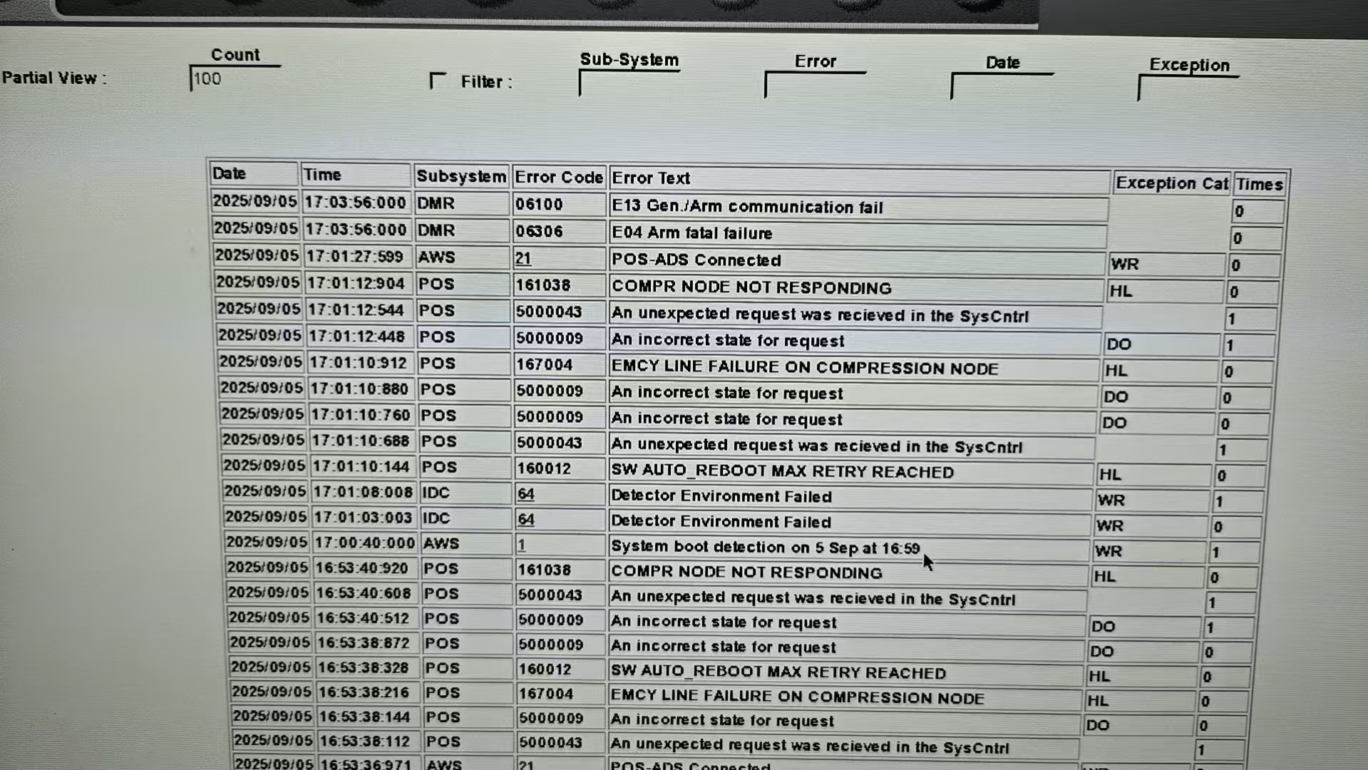
The gantry could not complete its startup and reset sequence.
The system reported E04 and E13, while the gantry display also showed H02, H35 and H17. Restarting the gantry and performing a complete system power cycle did not restore operation.
The key diagnostic clue was E13 — Gen./Arm Communication Fail — indicating that the problem could involve the communication path controlling the gantry rather than several unrelated mechanical failures.
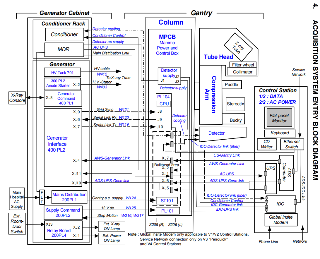
Follow the communication chain instead of treating each error independently.
Service documentation showed the command path as ADS Computer → Ethernet Switch → Gantry Interface Board (PL104) → Gantry CPU Board. The Gantry CPU Board then communicates through the PL104 interface to control the gantry. This architecture made the CPU board and PL104 interface board the primary suspects.
A CPU board replacement restored operation — temporarily.
The Gantry CPU Board was replaced and the system operated normally for a period of time. When the same failure returned, the recurrence showed that the underlying problem had not been eliminated.
This changed the troubleshooting direction from a single-board replacement to isolation of the common communication path.
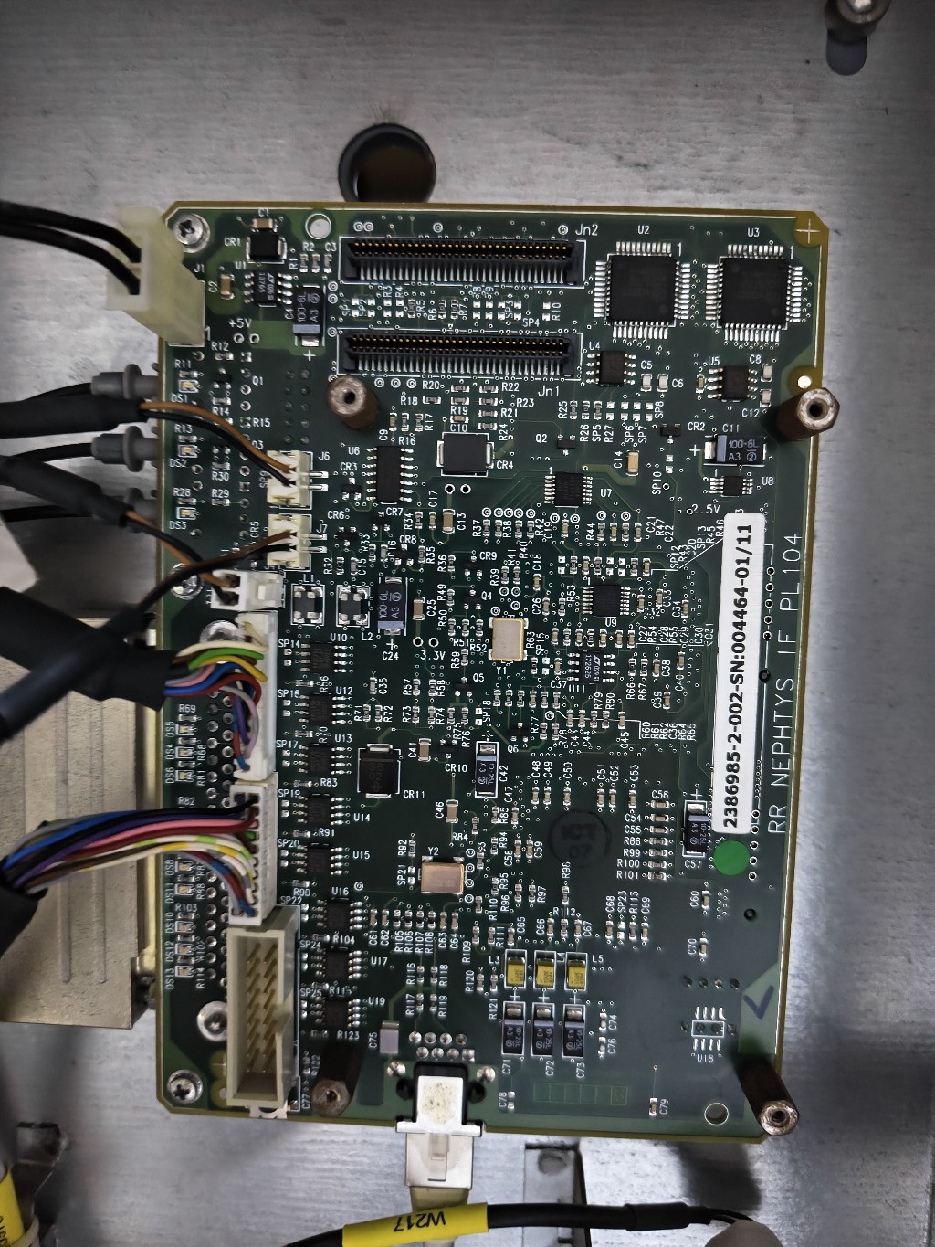
The PL104 Gantry Interface Board was isolated as the common failure point.
Further diagnosis identified the Gantry Interface Board (PL104) as the source of the recurring communication failure. The board was removed and repaired rather than replacing the entire gantry control subsystem.
- Reviewed system and gantry error history
- Verified that the failure persisted after restart and full power cycle
- Traced the ADS-to-gantry communication architecture
- Compared system behavior before and after CPU board replacement
- Isolated and repaired the PL104 interface board
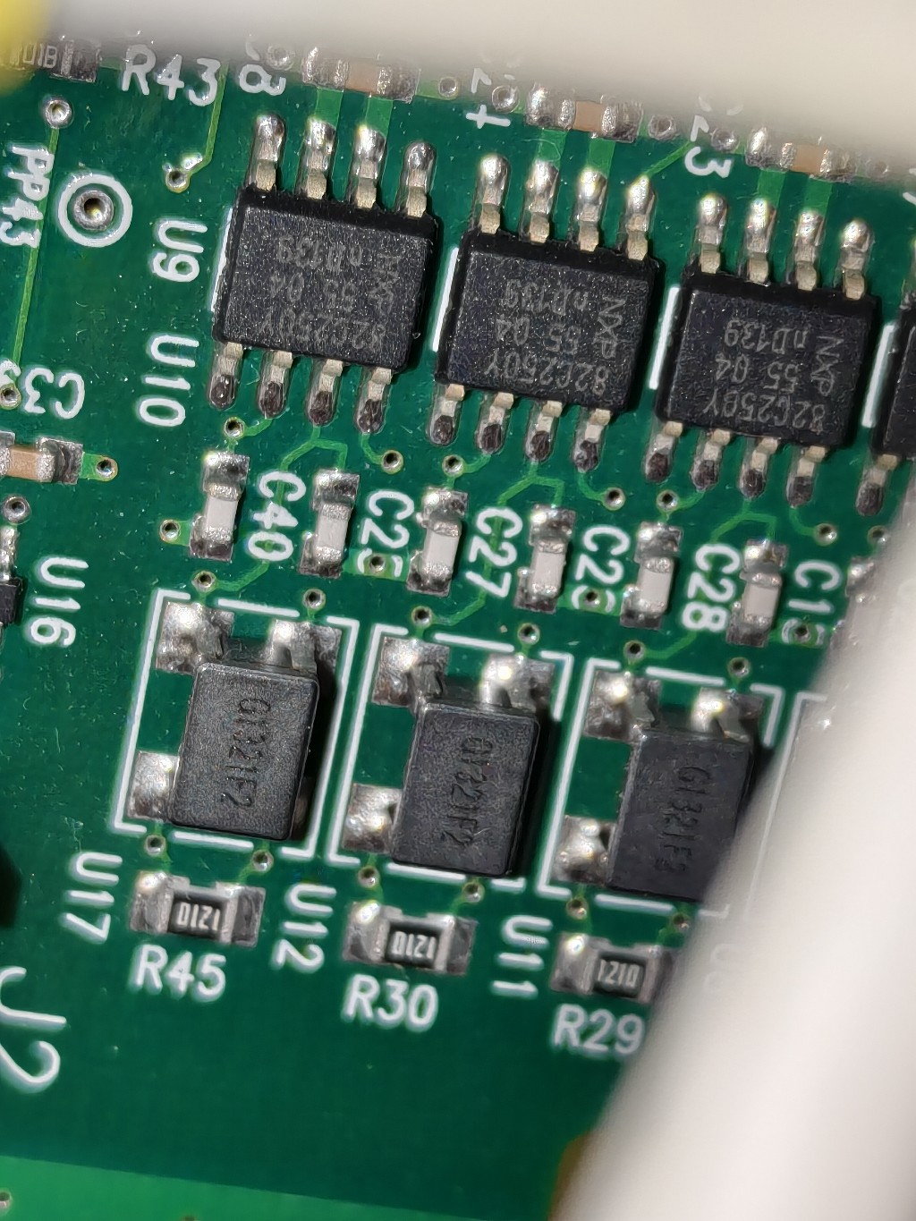
Normal gantry operation was restored after PL104 repair.
Following repair and reinstallation of the Gantry Interface Board, the machine returned to normal operation. The service record reports no abnormal operation after the repair.
Multiple error codes can originate from one common control path.
System architecture and fault isolation are often more valuable than replacing components one at a time. MIRRENO approaches electronic equipment repair by tracing signals, communications and subsystem dependencies to identify the failure point.
Have a Similar Equipment Failure?
Send us the error information, service documentation, board photos or failed electronic assembly. An engineer will review the problem and determine a practical diagnostic and repair path.
START A PROJECT →